DDS正弦信号发生器设计外文文献
本作品内容为DDS正弦信号发生器设计外文文献,格式为 doc ,大小 499200 KB ,页数为 17页
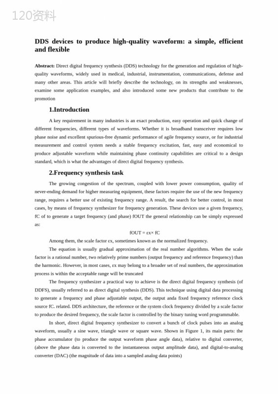
('DDSdevicestoproducehigh-qualitywaveform:asimple,efficientandflexibleAbstract:Directdigitalfrequencysynthesis(DDS)technologyforthegenerationandregulationofhigh-qualitywaveforms,widelyusedinmedical,industrial,instrumentation,communications,defenseandmanyotherareas.Thisarticlewillbrieflydescribethetechnology,onitsstrengthsandweaknesses,examinesomeapplicationexamples,andalsointroducedsomenewproductsthatcontributetothepromotion1.IntroductionAkeyrequirementinmanyindustriesisanexactproduction,easyoperationandquickchangeofdifferentfrequencies,differenttypesofwaveforms.Whetheritisbroadbandtransceiverrequireslowphasenoiseandexcellentspurious-freedynamicperformanceofagilefrequencysource,orforindustrialmeasurementandcontrolsystemneedsastablefrequencyexcitation,fast,easyandeconomicaltoproduceadjustablewaveformwhilemaintainingphasecontinuitycapabilitiesarecriticaltoadesignstandard,whichiswhattheadvantagesofdirectdigitalfrequencysynthesis.2.FrequencysynthesistaskThegrowingcongestionofthespectrum,coupledwithlowerpowerconsumption,qualityofnever-endingdemandforhighermeasuringequipment,thesefactorsrequiretheuseofthenewfrequencyrange,requiresabetteruseofexistingfrequencyrange.Aresult,thesearchforbettercontrol,inmostcases,bymeansoffrequencysynthesizerforfrequencygeneration.Thesedevicesuseagivenfrequency,fCoftogenerateatargetfrequency(andphase)fOUTthegeneralrelationshipcanbesimplyexpressedas:fOUT=εx×fCAmongthem,thescalefactorεx,sometimesknownasthenormalizedfrequency.Theequationisusuallygradualapproximationoftherealnumberalgorithms.Whenthescalefactorisarationalnumber,tworelativelyprimenumbers(outputfrequencyandreferencefrequency)thantheharmonic.However,inmostcases,εxmaybelongtoabroadersetofrealnumbers,theapproximationprocessiswithintheacceptablerangewillbetruncatedThefrequencysynthesizerapracticalwaytoachieveisthedirectdigitalfrequencysynthesis(ofDDFS),usuallyreferredtoasdirectdigitalsynthesis(DDS).Thistechniqueusingdigitaldataprocessingtogenerateafrequencyandphaseadjustableoutput,theoutputandafixedfrequencyreferenceclocksourcefC.related.DDSarchitecture,thereferenceorthesystemclockfrequencydividedbyascalefactortoproducethedesiredfrequency,thescalefactoriscontrolledbythebinarytuningwordprogrammable.Inshort,directdigitalfrequencysynthesizertoconvertabunchofclockpulsesintoananalogwaveform,usuallyasinewave,trianglewaveorsquarewave.ShowninFigure1,itsmainparts:thephaseaccumulator(toproducetheoutputwaveformphaseangledata),relativetodigitalconverter,(abovethephasedataisconvertedtotheinstantaneousoutputamplitudedata),anddigital-to-analogconverter(DAC)(themagnitudeofdataintoasampledanalogdatapoints)Figure2-1DDSfunctionofthesystemblockdiagram.Forthesinewaveoutput,relativetodigitalconverterisusuallyasinelookuptable(Figure2).PhaseaccumulatorunitcountNarelativetothefrequencyoffC,accordingtothefollowingequation:ThenumberofpulsesofthefC:Mistheresolutionofthetuningword(24-48)NcorrespondstothesmallestincrementofphasechangeofthephaseaccumulatoroutputwordFigure2-2TypicalDDSarchitectureandsignalpath(withDACs).ChangingNwillimmediatelychangetheoutputphaseandfrequency,sothesystemhasitsowncontinuousphasecharacteristics,whichisoneofthekeyattributesofmanyapplications.Noloopsettlingtime,whichisdifferentfromtheanalogsystem,suchasphase-lockedloops(PLLs).DACisusuallyahigh-performancecircuit,designedspecificallyfortheDDScore(phaseaccumulatorandphaseamplitudeconverter).Inmostcases,theresultsofthedevice(usuallysingle-chip)isgenerallyreferredtoasthepureDDSortheC-DDS.ActualDDSdevicesaregenerallymultipleregisters,inordertoachieveadifferentfrequencyandphasemodulationscheme.Suchasphaseregister,theirstoragephaseofincreaseintheoutputphaseofthephaseaccumulator.Inthisway,thecorrespondingdelayoutputsinewavephaseinaphasetuningword.Thisisusefulforphasemodulationapplicationsforcommunicationsystems.Theresolutionoftheaddercircuitdeterminesthenumberofbitsofthephasetuningword,therefore,alsodecidedtodelaytheresolution.IntegratedinasingledeviceontheengineofaDDSandaDAChasbothadvantagesanddisadvantages,however,whetherintegratedornot,needaDACtoproduceultra-highpurityhigh-qualityanalogsignal.DACwillconvertdigitalsinusoidaloutputtoananalogsinewavemaybesingle-endedordifferential.Someofthekeyrequirementsforlowphasenoise,excellentwideband(WB)andnarrowband(NB),spurious-freedynamicrange(SFDR),andlowpowerconsumption.Iftheexternaldevice,theDACmustbefastenoughtohandlethesignal,sothebuilt-inparallelportdeviceisverycommon.3.DDSandothersolutionsThefrequencyanalogphase-lockedloops(PLLs),clockgenerator,andtheuseofFPGAdynamicprogrammingoftheoutputoftheDAC.Byexaminingthespectrumofperformanceandpowerofthesetechnologies,asimplecomparison,Table1showsthequalitativeresultsofthecomparisonTable3-1DDSwithcompetingtechnologies-AdvancedcomparePowerconsumptionSpectralpurityRemarksDDSLowMiddleEaseoftuningDiscreteDAC+FPGAMiddleMiddle-HighWithtuningcapabilitiesAnalogPLLMilddleHighDifficulttuningPhase-lockedloopisafeedbackloopanditscomponents:aphasecomparator,adividerandapressure-controlledoscillator(VCO),phasecomparatorreferencefrequencyandoutputfrequency(usuallytheoutputfrequencyisN)frequency)werecompared.TheerrorvoltagegeneratedbythephasecomparatorisusedtoadjusttheVCO,thustheoutputfrequency.Whentheloopisestablished,theoutputfrequencyand/orphasewiththereferencefrequencytomaintainapreciserelationship.PLLhaslongbeenconsideredinaparticularfrequencyrange,highfidelityandconsistentsignallowphasenoiseandhighspuriousfreedynamicrange(SFDR)areidealforapplications.PLLcannotbepreciselyandquicklytuningthefrequencyoutputwaveform,andtheslowresponse,whichlimitstheirapplicabilityforfastfrequencyhoppingandpartofthefrequencyshiftkeyingandphaseshiftkeyingapplications.Otherprograms,includingintegratedDDSenginefieldprogrammablegatearrays(FPGAs)-asyntheticsinewaveoutputwiththeoff-the-shelfDAC-thoughthePLLfrequency-hoppingproblemcanbesolved,butthereownshortcomings.Thedefectsofthemajorsystemsworkandinterfacepowerrequirements,highcost,largesize,andsystemdevelopersmustalsoconsidertheadditionalsoftware,hardwareandmemory.Forexample,usingtheDDSengineoptioninthemodernFPGAtogeneratethe10MHzoutputsignaldynamicrangeis60dBupto72kBmemoryspace.Inaddition,designersneedtoacceptandbefamiliarwiththesubtlebalanceDDScorearchitecture..Fromapracticalpointofview(seeTable2),thankstotherapiddevelopmentofCMOStechnologyandmoderndigitaldesigntechniques,aswellastheimprovementoftheDACtopology,DDStechnologyhasbeenabletoachieveunprecedentedlowpowerconsumptioninawiderangeofapplications,spectrumperformanceandcostlevels.AlthoughthepureDDSproductsinperformanceanddesignflexibilitytoachievethelevelofhigh-endDACtechnologyandFPGA,buttheadvantagesofDDSintermsofsize,powerconsumption,costandsimplicity,makingittheprimarychoiceformanyapplications.Table3-2BenchmarkAnalysisSummary-frequencygenerationtechnique(<50MHz)Phase-lockedloopDAC+FPGADDSSpectralperformanceHighHighMiddleSystempowerrequirementsHighHighMiddleDigitalfrequencytuningNoYesYesTuningresponsetimeHighLowLowSolutionsizeMiddleHighLowWaveformflexibilityLowMiddleHighCostMiddleHighLowDesignreuseMiddleLowHighImplementationcomplexityMiddleHighLowAlsobenotedthattheDDSdevicefordigitalmethodstoproducetheoutputwaveform,itcansimplifysomeofthearchitectureofthesolution,orthewaveformofdigitalprogrammingtocreatetheconditions.UsuallywithasinewavetoexplainthefunctionsandworkingprincipleoftheDDS,butusingmodernDDSICscaneasilygenerateatrianglewaveorsquarewave(clock)output,therebyeliminatingtheformercasethelookuptable,andthelattercasetheDACtheneedtointegrateasimpleandaccurateenough.4.PerformanceandlimitationsoftheDDS4.1Imageandenvelope:Sin(x)xxroll-offTheactualoutputoftheDACisnotacontinuoussinewave,butaseriesofpulseswithasinusoidaltimeenvelope.Thecorrespondingspectrumisaseriesofimageandsignalaliasing.Imagealongthesin(x)/xenvelopedistribution(seeFigure3margingraph).Theneedforthefiltertosuppressfrequenciesoutsidethetargetband,butcannotinhibitthehigh-levelinthepassbandaliasing(forexample,causedduetoDACnon-linear)TheNyquistcriterionrequiresthateachcyclerequiresatleasttwosamplingpointsinordertorebuildthedesiredoutputwaveform.TheMirroringresponsearisingfromsamplingtheoutputfrequencyK,CLOCK×OUTInthisexample,whichCLOCK=2525MHzandfOUT=5MHz,thefirstandsecondmirrorfrequencyappearin(seeFigure3)fCLOCK×fOUT,o20MHzand30MHz.Thethirdandfourthmirrorfrequencyat45MHzand55MHz.Note,sin(x)/xvalueofzeroatmultiplesofthesamplingfrequency.WhenfOUTgreaterthantheNyquistbandwidth(1/2fCLOCK),thefirstmirrorfrequencywillappearintheNyquistbandwidth,theoccurrenceofaliasing(suchas15MHzsignalaliasingdownto10MHz).Cannotusethetraditionalquistanti-aliasingfiltertofilteroutaliasingmirrorfrequencyfromtheoutputFigure4-1Sin,inFigure3.DDS,(x)/xroll-off.InatypicalDDSapplication,theuseofalow-passfiltertosuppressthemirrorfrequencyresponseoftheoutputspectrum.Tomakethelow-passfiltercutofffrequencytoremainatreasonablelevels,andkeepitsimplefilterdesign,afeasibleapproachistheuseofaneconomiclow-passoutputfilterbandwidthlimitedtoabout40%ofthefrequencyofclock.Anygivenmirrorfrequencyrelativetotheamplitudeofthefundamentalformulaofsin(x)/xcalculation.Becausethefunctionofthefrequencyroll-off,thebasicoutputoftheamplitudeandtheoutputfrequencyisinverselyproportionaltodecrease;intheDDSsystem,reducetheamountofDC-Nyquistbandwidthrangeof-3.92dB.Significantreductioninfrequencyinthefirstmirror-thefundamental3dBrange.InordertosimplifytheDDSapplicationfiltering,frequencyplanmustbeformulatedandanalyzedtomirrorthefrequencyandmagnitudeofthesin(x)/xresponseintheOUTandCLOCKtargetfrequencyspectrumrequirements.Otherunwantedfrequenciesintheoutputspectrum(suchasintegralanddifferentiallinearityerroroftheDAC,thesurgeofenergyassociatedwiththeDACandclockfeedthroughnoise)doesnotfollowthesin(x)/xroll-offresponse.Theseunwantedfrequencieswillbeharmonicandspuriousenergyintheoutputspectruminmanyplaces-butitsmagnitudeisgenerallyfarbelowthemirrorfrequencyresponse.DDSdevicestothegeneralbackgroundnoise,substratenoise,thermalnoiseeffects,groundcouplingandothersignalsourcecouplingfactorcumulativeportfoliodecisions.DDSdevices,thenoisefloorperformanceofstrayandjitterbythecircuitboardlayout,powerquality,and-mostimportantly-Entertheprofoundimpactofthequalityofthereferenceclock.4.2ShakeTheedgeoftheperfectclocksourcewillbetheprecisetimeinterval,theintervalwillneverchange.Ofcourse,thisisnotpossible;eventhebestoscillatorisalsotheidealcomponentsconstitute,withnoiseandotherdefects.Qualityandlowphasenoisecrystaloscillatorjitterpicosecond,andisbuiltupfromonemillionthenumberofclockedge.Thefactorsleadingtojitterexternalinterference,thermalnoise,theoscillatorcircuitinstabilityandpower,groundandoutputconnectionsbring,allthesefactorswillinterferewiththetimingcharacteristicsoftheoscillator.Inaddition,theoscillatorbytheexternalmagneticfieldorelectricfieldandthenearbytransmitterRFinterference.Oscillatorcircuit,asimpleamplifier,inverterorbuffertosignaladditionaljitter.Therefore,thechoiceofalow-jitter,andtheedgeofsteepstablereferenceclockoscillatoriscritical.Higherfrequencyreferenceclockallowsalargersample,anddividetosomeextent,reducethejitter,becausethesignaltodividealongtimetoproducethesameamountofjitter,whichcanreducethejitteronthesignalpercentage.4.3Noise-includingthephasenoiseThesamplingsystemnoisedependsonmanyfactors,themostimportantfactoristhereferenceclockjitter,thisjitterperformanceofphasenoiseonfundamentalsignal.IntheDDSsystem,theregisteroutputofthetruncatedphasemaybringthesystemerrorcode.Thebinaryworddoesnotleadtothetruncationerror.Butfornon-binaryword,phasenoisetruncationerrorinthespectrumspurious.Spuriousfrequency/amplitudedependsonthecodeword.QuantificationandlinearityerroroftheDACwillbebroughttothesystemharmonicnoise.Time-domainerror(suchasowedtothered/overshootandcodeerrors)willincreasetheoutputsignaldistortion.5.Application5.1DDSapplicationscanbedividedintotwocategories:Requireagilefrequencysourcefordatacodingandmodulationapplications,communicationsandradarsystemsRequiremeasurementoftheuniversalfrequencysynthesizerfeaturesandprogrammabletuning,scanning,andmotivationalskills,industrialandopticalapplicationsBothcases,thetrendtowardhigherspectralpurity(lowphasenoiseandhigherspuriousfreedynamicrange),alsolowpowerandsmallsizerequirementstoaccommodatetheremoteordemandforbattery-powereddevices.5.2Modulation/dataencoding,andsynchronizationoftheDDSDDSproductsfirstappearedontheradarandmilitaryapplicationsandthedevelopmentofsomeofitscharacteristics(performanceimprovements,costandsize,etc.)DDStechnologyisbecomingmoreprevalentinthemodulationanddataencodingapplications.ThissectionwilldiscussthetwodataencodingschemeintheDDSsystem.5.3BinaryfrequencyshiftkeyingThelaunchofthedataisacontinuouscarrierfrequencyintwodiscretefrequency(binaryone,ie,passnumber,abinary0,namely,thetransformationbetweenthespace).Figure4showstherelationshipbetweenthedataandtransmitsignals.Figure5-1binaryFSKmodulation.Binary1and0fortwodifferentfrequenciesf0andf1,respectively.ThisencodingschemecanbeeasilyDDSdevice.OnbehalfoftheoutputfrequencyoftheDDSfrequencytuningwordchangetof0andf1,willlaunchthe1and0.TotransformtheoutputfrequencyshalldedicatedpinFSELECT,containingtheappropriatetuningwordregisters(seeFigure5)Figure5-2AD9834orAD9838DDStuningwordselectorrealizationoftheFSKencoding.5.4Phaseshiftkeying(PSK)InPSK,thecarrierfrequencyremainsthesame,bychangingthephaseofthetransmittedsignaltotransmitinformation.CantakeadvantageofavarietyofprogramstoachievePSK,.TheeasiestwayisoftenreferredtoasbinaryPSK(BPSK),usingonlytwosignalphase:0°(logic1)and180°(logic0).Membersstatedependsonthestatusoftheformerone.Ifthewavephaseremainsunchanged,thesignalstatewillremainthesame(loworhigh).Wavephasechange180°,ie,phaseinversion,thesignalstatewillchange(lowintohighorhightolow).PSKcodinginDDSproductscanbeeasilyachieved,becausemostdeviceshaveaseparateinputregister(phaseregister),andphasevaluescanbeloaded.Thisvalueisaddeddirectlytothecarrierphase,withoutchangingitsfrequency.Changethecontentsoftheregisterwillbemodulatedcarrierphase,resultinginaPSKoutput.Forapplicationsthatrequirehigh-speedmodulation,built-inphaseregisteroftheAD9834andAD9838allowPSELECTpinsignaltransformation,accordingtoneedmodulatedcarrierinthepreloadedphaseregisters.ThemorecomplexthePSKfouroreight-wavephase.Thus,wheneverthephasechangeofbinarydatatransferratewillbehigherthantheBPSKmodulation.Inthefour-phasemodulation(QuadraturePSK),inthephaseangleof0°to+90°,-90°and+180°;eachphasetotransformthetwosignalsmayrepresentafactorAD9830,AD9831,AD9832,andtheAD9835providesfourphaseregisters,canbecontinuouslyupdatedregisterofdifferentphaseshift,thecomplexphasemodulationscheme.5.5TheuseofsynchronousmodeofmultipleDDSdevicestoachievetheI/QMultipleDDScomponentstoachievethemanyapplicationsoftheI/Qsinewaveorsquarewavesignalofknownphaserelationshipbetweentwoormoresynchronousmode.Acommonexampleisthesamephaseandquadraturemodulation(I/Q)inthistechnique,thephaseangleof0°and90°fromthecarrierfrequencysignalinformation.ToruntwoseparateDDScomponents,youcanusethesamesourceclocktooutputcandirectlycontrolandmanipulatethesignalofthephaserelationship.InFigure6,withareferenceclockontheAD9838deviceprogramming;theRESETpinisusedtoupdatethetwodevices.Inthisway,youcanachieveasimpleI/QmodulationRESETafterpowerandinitializedbeforeanydatatotheDDStransmission.DDSoutputresultscanbeplacedinaknownphase,makingitacommonreferencepointofview,inordertosynchronizemultipleDDSdevices.WhennewdataissenttomultipleDDSdevices,theDDScanremainrelevantphaserelationship,orbythephaseoffsetregistercanpredicttherelativephaseshiftbetweentheadjustmentsofmultipleDDS.TheAD983xseriesofDDSproductshavea12phaseresolution,theeffectiveresolutionof0.1°.Figure5-3SynchronizethetwoDDScomponents.DDS器件产生高质量波形:简单、高效而灵活摘要:直接数字频率合成(DDS)技术用于产生和调节高质量波形,广泛用于医学、工业、仪器仪表、通信、国防等众多领域。本文将简要介绍该技术,说明其优势和不足,考察一些应用示例,同时介绍一些有助于该技术推广的新产品。1.简介许多行业中一个关键的需求是精确产生、轻松操作并快速更改不同频率、不同类型的波形。无论是宽带收发器要求具有低相位噪声和出色的无杂散动态性能的捷变频率源,还是工业测量和控制系统需要稳定的频率激励,快速、轻松、经济地产生可调波形并同时维持相位连续性的能力都是至关重要的一项设计标准,而这正是直接数字频率合成技术的优势所在。频率合成的任务。不断增多的频谱拥堵,加上对功耗更低、质量更高的测量设备的永无止境的需求,这些因素都要求使用新的频率范围,要求更好地利用现有频率范围。结果,人们寻求对频率产生进行更好的控制,多数情况下,均是借助于频率合成器.这些器件利用一个给定频率,fC来产生一个相关的目标频率(和相位)fOUT.其一般关系可以简单地表示为:fOUT=εx×fC其中,比例因子εx,有时也被称为归一化频率.该等式通常利用实数逐步逼近的算法实现。当比例因子为有理数时,两个相对质数(输出频率和基准频率)之比将谐波相关。但在多数情况下,εx可能属于更广泛的实数集,逼近过程一旦处于可接受的范围之内即会被截断。2.直接数字频率合成频率合成器的一种实用型实现方式是直接数字频率合成(DDFS),通常简称为直接数字合成(DDS).这种技术利用数字数据处理来产生一个频率和相位可调的输出,该输出与一个固定的频率参考或时钟源fC.相关。在DDS架构中,参考或系统时钟频率由一个比例因子分频来产生所需频率,该比例因子由二进制调谐字可编程控制。简言之,直接数字频率合成器将一串时钟脉冲转换成一个模拟波形,通常为一个正弦波、三角波或方波。如图1所示,其主要部分为:相位累加器(产生输出波形相位角度的数据),相数转换器,(将上述相位数据转换为瞬时输出幅度数据),以及数模转换器(DAC)(将该幅度数据转换成采样模拟数据点)。图2-1DDS系统的功能框图对于正弦波输出,相数转换器通常为一个正弦查找表(图2)。相位累加器以N为单位计数,并根据以下等式产生一个相对于fC的频率:其中:M为调谐字的分辨率(24至48位)N为对应于相位累加器输出字最小增量相位变化的fC的脉冲数图2-2典型的DDS架构和信号路径(带DAC)由于更改N会立即改变输出相位和频率,因此,系统自身具有相位连续,特点,这是许多应用的关键属性之一。无需环路建立时间,这与模拟系统不同,如锁相环(PLL)。DAC通常为一个高性能电路,专门针对DDS内核(相位累加器和相幅转换器)而设计。多数情况下,这样结果形成的器件(通常为单芯片)一般称为纯DDS或C-DDS。实际的DDS器件一般集成多个寄存器,以实现不同的频率和相位调制方案。如相位寄存器,其存储的相位内容被加在相位累加器的输出相位上。这样,可以对应于一个相位调谐字延迟输出正弦波的相位。对于通信系统相位调制应用,这非常有用。加法器电路的分辨率决定着相位调谐字的位数,因此,也决定着延迟的分辨率。在单个器件上集成一个DDS引擎和一个DAC既有优点也有缺点,但是,无论集成与否,都需要一个DAC来产生纯度超高的高品质模拟信号。DAC将数字正弦输出转换为一个模拟正弦波,可能是单端,也可能是差分。一些关键要求是低相位噪声、优秀的宽带(WB)和窄带(NB)无杂散动态范围(SFDR)以及低功耗。如果是外部器件,则DAC必须足够快以处理信号,因此,内置并行端口的器件非常常见。3.DDS与其他解决方案其他产生频率的方法包括模拟锁相环(PLL),时钟发生器和利用FPGA对DAC的输出进行动态编程。通过考察频谱性能和功耗,可以对这些技术进行简单的比较,表1以定性方式展示了比较结果。表3-1DDS与竞争技术——高级比较功耗频谱纯度备注DDS低中易于调谐分立式DAC+FPGA中中-高具有调谐能力模拟PLL中高难以调谐锁相环是一种反馈环路,其组成部分为:一个相位比较器,一个除法器和一个压控制振荡器(VCO).相位比较器将基准频率与输出频率(通常是输出频率的N)分频)进行比较。相位比较器产生的误差电压用于调节VCO,从而输出频率。当环路建立后,输出将在频率和/或相位上与参考频率保持一种精确的关系。PLL长期以来一直被认为是在特定频带范围内要求高保真度和稳定信号的低相位噪声和高无杂散动态范围(SFDR)应用的理想选择。由于PLL无法精确、快速地调谐频率输出和波形,而且响应较慢,这限制了它们对于快速跳频和部分频移键控和相移键控应用的适用性。其他方案,包括集成DDS引擎的现场可编程门阵列(FPGAs)——配合现成DAC以合成输出正弦波——虽然可以解决PLL的跳频问题,但也存在自身的缺陷。主要系统缺陷包括较高的工作和接口功耗要求、成本较高、尺寸较大,而且系统开发人员还须考虑额外的软件、硬件和存储器问题。例如,利用现代FPGA中的DDS引擎选项,要产生动态范围为60dB的10MHz输出信号,需要多达72kB的存储器空间。另外,设计师需要接受并熟悉细微权衡和DDS内核的架构。从实用角度来看(见表2),得益于CMOS工艺和现代数字设计技术的快速发展以及DAC拓扑结构的改进,DDS技术已经能在广泛的应用中实现前所未有的低功耗、频谱性能和成本水平。虽然纯DDS产品不可能在性能和设计灵活性上达到高端DAC技术与FPGA相结合的水平,但DDS在尺寸、功耗、成本和简单性方面的优势使其成为许多应用的首要选择。表3-2基准分析小结——频率产生技术(<50MHz)锁相环DAC+FPGADDS频谱性能高高中系统功耗要求高高低数字频率调谐无是是调谐响应时间高低低解决方案尺寸中高低波形灵活性低中高成本中高低设计重用中低高实现复杂度中高低同时需要指出,由于DDS器件从根本上来说是用数字方法产生输出波形,因此它可以简化一些解决方案的架构,或者为对波形进行数字化编程创造条件。尽管通常利用正弦波来解释DDS的功能和工作原理,但利用现代DDSIC也可以轻松产生三角波或方波(时钟)输出,由此消除了前一种情况的查找表以及后一种情况的DAC的必要性,因为集成一个简单而精确的比较器就够了。4.DDS的性能与限制4.1图像和包络:Sin(x)xx滚降DAC的实际输出不是连续的正弦波,而是带有正弦时间包络的一系列脉冲。对应的频谱是一系列图像和混叠信号。图像沿sin(x)/x包络分布(见图3中的幅度曲线图)。有必要进行滤波,以抑制目标频带之外的频率,但是不能抑制通带中出现的高阶混叠(例如,因DAC非线性所致)。奈奎斯特准则要求,每个周期至少需要两个采样点才能重建所需输出波形。镜像响应产生于采样输出频率中KfCLOCK×fOUT.在本例中,其中fCLOCK=2525MHz且fOUT=5MHz,第一和第二镜频出现在(见图3)fCLOCK×fOUT,o即20MHz和30MHz。第三和第四镜频出现在45MHz和55MHz。注意,sin(x)/x零值出现在采样频率的倍数处。当fOUT大于奈奎斯特带宽(1/2fCLOCK),时,第一镜频将出现于奈奎斯特带宽之内,发生混叠(例如,15MHz的信号将向下混叠至10MHz)。无法用传统的奈奎斯特抗混叠滤波器从输出中滤掉混叠镜频。图4-1DDS中的Sin(x)/x滚降在典型的DDS应用中,利用一个低通滤波器来抑制输出频谱中镜频响应的影响。为了使低通滤波器的截止频率要求保持于合理水平,并使滤波器设计保持简单,一种可行的做法是利用一个经济的低通输出滤波器将fOUT带宽限制在fCLOCK频率的40%左右。任何给定镜频相对于基波的幅度可用sin(x)/x公式来计算。由于该函数随频率滚降,因此基本输出的幅度将与输出频率成反比而降低;在DDS系统中,降低量为DC-奈奎斯特带宽范围的–3.92dB。第一镜频的幅度较大——基波的3dB范围内。为了简化DDS应用的滤波要求,必须制定频率计划,并分析镜频和sin(x)/x幅度响应在fOUT和fCLOCK目标频率下的频谱要求。输出频谱中的其他不需要的频率(如DAC的积分和微分线性误差、与DAC相关的突波能量和时钟馈通噪声)不会遵循sin(x)/x滚降响应。这些不需要的频率将以谐波和杂散能量出现在输出频谱中的许多地方——但其幅度一般会远远低于镜频响应。DDS器件的一般本底噪声由基板噪声、热噪声效应、接地耦合和其他信号源耦合等因素累积组合决定。DDS器件的本底噪声、性能杂散和抖动受到电路板布局、电源质量以及——最重要的是——输入参考时钟。4.2抖动完美时钟源的边沿将以精确的时间间隔发生,而该间隔永远都不会变化。当然,这是不可能的;即使最好的振荡器也是由不理想的元件构成,具有噪声等缺陷。优质的低相位噪声晶体振荡器的抖动为皮秒级,而且是从数百万个时钟边沿累积起来的。导致抖动的因素有热噪声、振荡器电路不稳定以及电源、接地和输出连接等带来的外部干扰等,所有这些因素都会干扰振荡器的时序特性。另外,振荡器受外部磁场或电场以及附近发射器的射频干扰的影响。振荡器电路中,一个简单的放大器、反相器或缓冲器也都会给信号带来额外的抖动。因此,选择一个抖动低、边沿陡的稳定的参考时钟振荡器是至关重要的。较高频率的基准时钟允许较大的过采样,而且,通过分频可以在一定程度上减轻抖动,因为对信号进行分频将在更长时期产生相同量的抖动,因而可以降低信号上的抖动的百分比。质量的深刻影响。4.3噪声——包括相位噪声采样系统的噪声取决于诸多因素,首要因素是参考时钟抖动,这种抖动表现为基波信号上的相位噪声。在DDS系统中,截断相位寄存器输出可能带来因代码而异的系统误差。二进制字不会导致截断误差。但对于非二进制字,相位噪声截断误差会在频谱中产生杂散。杂散的频率/幅度取决于代码字。DAC的量化和线性误差也会给系统带来谐波噪声。时域误差(如欠冲/过冲和代码错误)都会加重输出信号的失真。5应用5.1DDS应用可以分为两大类:(1)要求捷变频率源以进行数据编码和调制应用的通信和雷达系统(2)要求通用频率合成功能以及可编程调谐、扫描和激励能力的测量、工业和光学应用两种情况下,都出现了一种走向更高频谱纯度(更低的相位噪声和更高的无杂散动态范围)的趋势,同时还存在低功耗和小尺寸的要求,以适应远程或电池供电设备的需求。5.2调制/数据编码和同步中的DDSDDS产品首先出现于雷达和军事应用之中,其部分特性的发展(性能的提升、成本和尺寸等)已使DDS技术在调制和数据编码应用中日渐盛行。本节将讨论两种数据编码方案及其在DDS系统中的实现方式。5.3二进制频移键控(BFSK,或简称FSK)数据的发射方式是使一个连续载波的频率在两个离散频率(一为二进制1,即传号,一为二进制0,即空号)之间变换。图4所示为数据和发射信号之间的关系。图5-1二进制FSK调制二进制1和0表示为两个不同的频率,分别为f0和f1。这种编码方案可以轻松在DDS器件中实现。代表输出频率的DDS频率调谐字被改变,以从将发射的1和0产生f0和f1。要变换输出频率,则须用专用的引脚FSELECT选择含有相应调谐字的寄存器(见图5)。图5-2利用AD9834或AD9838DDS的调谐字选择器实现FSK编码5.4相移键控(PSK)是另一种简单的数据编码形式。在PSK中,载波的频率保持不变,通过改变发射信号的相位来传递信息。可以利用多种方案来实现PSK。最简单的方法通常称为二进制PSK(即BPSK),只采用两个信号相位:0°(逻辑1)和180°(逻辑0)。各位的状态取决于前一位的状态。如果波的相位不变,则信号状态将保持不变(低或高)。如果波的相位改变180°,即相位反转,则信号状态将改变(低变为高,或高变为低)。PSK编码可以轻松在DDS产品中实现,因为多数器件都有一个独立的输入寄存器(相位寄存器),可以加载相位值。该值被直接添加到载波的相位,而不改变其频率。更改该寄存器的内容将调制载波的相位,结果产生一个PSK输出。对于要求高速调制的应用,内置相位寄存器对的AD9834和AD9838允许其PSELECT引脚上的信号在预加载的相位寄存器之间变换,以根据需要调制载波。更复杂的PSK采用四个或八个波相位。这样,每当相位发生变化时,二进制数据的传输速率将高于BPSK调制。在四相位调制(正交PSK),中,可能的相位角度为0°,+90°,−90°,和+180°;每次相位变换可能代表两个信号因子AD9830,AD9831,AD9832,和AD9835提供四个相位寄存器,通过连续更新寄存器的不同相位偏移,可以实现复杂的相位调制方案.。5.5以同步模式利用多个DDS元件实现I/Q功能许多应用要求产生两个或两个以上具有已知相位关系的正弦波或方波信号。一个常见的例子是同相和正交调制(I/Q),在这种技术中,在0°和90°相位角度从载波频率获得信号信息。可以用相同的源时钟来运行两个单独的DDS元件,以输出可以直接控制和操作其相位关系的信号。在图6中,用一个基准时钟对AD9838器件编程;相同的RESET引脚用于更新两个器件。这样,可以实现简单的I/Q调制。RESET必须在上电后以及向DDS传输任何数据之前初始化。结果可将DDS输出置于已知相位,使其成为共同的参考角度,以便同步多个DDS器件。当新数据被同时送至多个DDS器件时,DDS之间可以保持相关相位关系,或者通过相位偏移寄存器可以预测性调整多个DDS之间的相对相位偏移。AD983x系列DDS产品拥有12位相位分辨率,有效分辨率为0.1°。图5-3同步两个DDS元件',)
提供DDS正弦信号发生器设计外文文献会员下载,编号:1700817243,格式为 docx,文件大小为17页,请使用软件:wps,office word 进行编辑,PPT模板中文字,图片,动画效果均可修改,PPT模板下载后图片无水印,更多精品PPT素材下载尽在某某PPT网。所有作品均是用户自行上传分享并拥有版权或使用权,仅供网友学习交流,未经上传用户书面授权,请勿作他用。若您的权利被侵害,请联系963098962@qq.com进行删除处理。

 下载
下载 下载
下载 下载
下载 下载
下载 下载
下载 下载
下载 下载
下载 下载
下载 下载
下载 下载
下载 下载
下载 下载
下载